Carrier Monitoring

SkyMon is a sophisticated, fully-automated radio frequency traffic monitoring system, which provides you with all the necessary tools for continually monitoring the links between your satellites and your ground stations from one central hub, obviating the need for investments at your various locations around the globe.
SkyMon improves the capability of satellite providers/telecom companies to react promptly and effectively to anomaly events and to provide assistance for activities, such as controlling access to the satellites (carrier line-ups) and solving problems (e.g. analyzing interference and carrier performance).
Benefits

One system for all ground stations and satellites
The most outstanding feature of SkyMon is its multisite capability. All monitoring sites can be combined to a single point-controlled system. This means that you can monitor and control all your traffic from all your satellites with one single system. The client-server architecture allows client applications to be connected anywhere on the network. Measurements can be performed at any site and merged together.
Lower investment expenditure thanks to optimal use of resources
SkyMon puts the monitoring resources (i.e. monitoring antennas and measuring devices) in the configuration database to optimum use. The way these resources are managed is totally automatic and transparent to the user. For each measurement the system selects the monitoring resources from the pool of available resources based on the configuration data.

Reuse of existing infrastructure
SkyMon supports a wide range of monitoring equipment, like spectrum analyzers, down converters, switching units, etc. For more information, see “Measurement devices”. Thanks to the modular concept of the system architecture, upgrading to new equipment can be done at any time by adding plug-in modules to the system without having to change the SW kernel. All users can upgrade their systems by simply purchasing new module licenses.

Easily adaptable to support the daily tasks of operators
Since SkyMon was developed in cooperation with satellite operators, its architecture and functionality is optimized to support users in their daily tasks. Different reports are defined to make it easier for users to create reports from archived data up to the latest measurements that have not even been stored in a database. Measurement parameter settings (instrument settings, path description) are stored together with the measurements and are used for reports.
Key features

Automatic background mode
Monitors the traffic in a round-robin fashion – 24 hours a day, 7 days a week – without any operator interaction. Background monitoring is automatically distributed to all monitoring sites and rescheduled if one site fails.

Active foreground mode

Hidden carrier detection
The system evaluates the error vector signal, which enables detection of interfering in-band spurious signals without deteriorating ongoing transmissions. The underlying carrier noise and interference spectra are presented in the same display plot that also shows the measured carrier spectra, separated by different colors.

Interference localization
Architecture
In single-site architectures, all SkyMon components can be installed on one single unit, the so-called SkyMon BOX. It combines the entire SkyMon monitoring software with a powerful DSP monitoring device on one single rack-mounted server.
In addition to the integrated DSP monitoring device, SkyMon supports a lot of COTS DSP or swept-spectrum analyzers. This permits the configuration of several monitoring devices even in single-site architectures.
The most outstanding feature of SkyMon is its multisite capability. All monitoring sites can be combined (e.g. via Internet (VPN) or a customer’s Wide Area Network) to a single point-controlled system. The client-server architecture allows client applications to be connected anywhere on the network. The multi-site interface component allows measurements to be performed at any site and then merged together.
Background monitoring is automatically distributed to all monitoring sites and re-scheduled if one site fails.
Applications
The system offers a wide range of useful applications to the operator. Each system consists of the basic carrier monitoring functionalities, which provide the operator with basic RF measurements, like spectrum monitoring, measurement of power, center frequency, bandwidth, etc.
On top of the basic carrier monitoring functionalities the system also offers enhanced applications, like DSP measurements or transponder performance monitoring.
Basic Carrier Monitoring
The SkyMon Base system offers operators the most useful foreground modes for basic carrier monitoring:
Real-time carrier mode
Gives the operator limited control of a manually-selected monitoring device. In this mode, SkyMon allows resource sharing for this monitoring device. Basically, the real-time carrier mode permits defining the most important settings of a monitoring device to be able to visualize the spectrum of the signal received by that device and to store/retrieve the displayed spectra.
Selected carrier mode
Automatic Background Mode
In the background mode SkyMon continuously monitors the traffic defined in the space segment configuration in a round-robin fashion, i.e. each satellite, transponder and carrier (or group of carriers) is scanned separately for each polarization in ascending order, according to its frequency.
SkyMon puts the monitoring resources (i.e. monitoring antennas and devices) assigned to the background mode in the configuration database to optimum use. The way these resources are managed is totally automatic and transparent to the user. For each measurement the system selects the monitoring resources from the ones available in accordance with the configuration data.
For each background monitoring scan SkyMon stores the measurement data in the measurement database and checks them against configurable thresholds. An event or alarm is triggered if the threshold limits are exceeded.
Foreground Measurements
In addition to the real-time carrier and selected carrier modes, which are part of the SkyMon Base, the system offers additional foreground modes:
- DSP Selected Carrier Mode
- Selected Band Mode
- Line-Up Mode
DSP Selected Carrier Mode

Similar to the Selected Carrier Mode, the DSP Selected Carrier Mode supports continuous monitoring of a user-defined group of digital carriers. Other than with the Selected Carrier Mode functionality, the measurements are performed by automatically demodulating and decoding each carrier to get the measurement results.
Furthermore, this measurement mode provides carrier-cross-polarization discrimination measurements by simultaneously acquiring co- and cross-polarization signals, followed by correlation signal processing. This approach provides accurate XPDM results without interruption of operational services (no need to switch to CW mode, no need to ‘see’ the carrier signal on the xpol spectrum). Thanks to the signal processing applied, this measurement is independent of noise and/or leakage from cross-polarization traffic.
Selected Band Mode

In this mode the system executes a one-shot scanning of a transponder or transponder portion selected by the user and performs the same types of measurements as those relevant for the background mode, including spurious signal detection.
Line-Up Mode
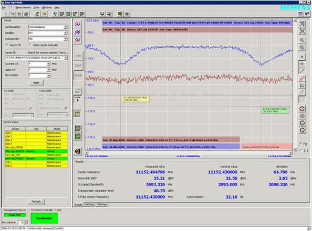
 This mode is specifically designed to assist the operator during line-up activities. It provides continuous scanning of the portion of a transponder that hosts the carrier to be up-linked (lined up). The Line-Up Mode itself consists of three sub-modes, referred to as: CW, CW-EDF and Modulated Line-Up Mode.
Visualization of both the co-polar and the cross-polar spectra on one single screen, together with the measured polarization isolation:
It is possible to ensure simultaneous measurement of the cross-polar and copular values from two different sites and at different center frequencies. The system automatically selects the setting of the monitoring device.
DSP Measurements
Carrier Monitoring Systems are used for supervision of the radio traffic in satellite communication systems. Due to the use of new modulation techniques and dynamically changing traffic situations, monitoring systems are increasingly employed to support the operator with enhanced analyses tools as well as improved demodulation and automatic carrier detection methods.
The foreseeable increase of satellite channels in the near future will force satellite operators to carefully supervise signals for being able to guarantee high signal qualities to their users. Hence, speed of measurement, flexibility in measuring a great variety of signal parameters, including baseband demodulation parameters and cost-efficient solutions, will be necessary. For this purpose, SkyMon provides additional information (characterization of carriers and additional measurement results) and an analysis feature (blind scanning, signal-under-carrier detection and measurement, compression point analysis, etc.). In addition, SkyMon measurement speed will be significantly increased by DSP signal analyzers.
Blind scanning
Detected Carrier Selection and Transfer to the DB
SkyMon DSP demodulation permits automatic detection of data rates and modulation schemes of individual carriers. In order to provide high modulation recognition, the relevant algorithms are designed to identify the relevant demodulation schemes (BPSK, QPSK, 8PSK, 16QAM, etc.) and demodulation parameters (symbol rate, shaping filter, roll-off, center frequency, etc.). The individual carriers and their demodulation parameters are presented in the selected band result list together with the already existing RF measurement results.
Signal-under-carrier detection
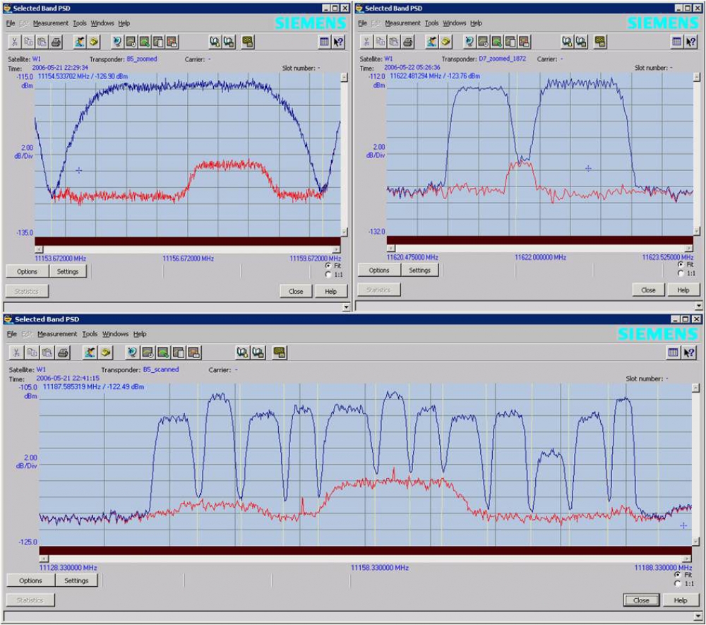
This feature offers troubleshooting in case of cross-polarization interference or locally generated interference, while the carrier remains in service. Providing the error vector magnitude spectra enhances the automatic as well as user-initiated foreground-monitoring modes with in-band noise and interference measurement capabilities, while the desired carriers remain in service. Therefore, the system evaluates the error vector signal, which enables the detection of interfering in-band spurious signals without deteriorating the ongoing transmission. The carrier underlying noise and interference spectra are presented in the same display plot as the measured carrier spectra, separated by different colors.
In the screenshot above you will find several examples of an interference spectrum (displayed in red), computed from the measured spectra (displayed in blue). What is particularly remarkable in this example is that the hidden carrier spectra (signal under carrier) are also calculated outside the carrier symbol rate frequency ranges and therefore seamlessly concatenated in order to provide successful identification of interference, even if other carriers are affected simultaneously. This algorithm is filed for patent.
Automatic Path Calibration
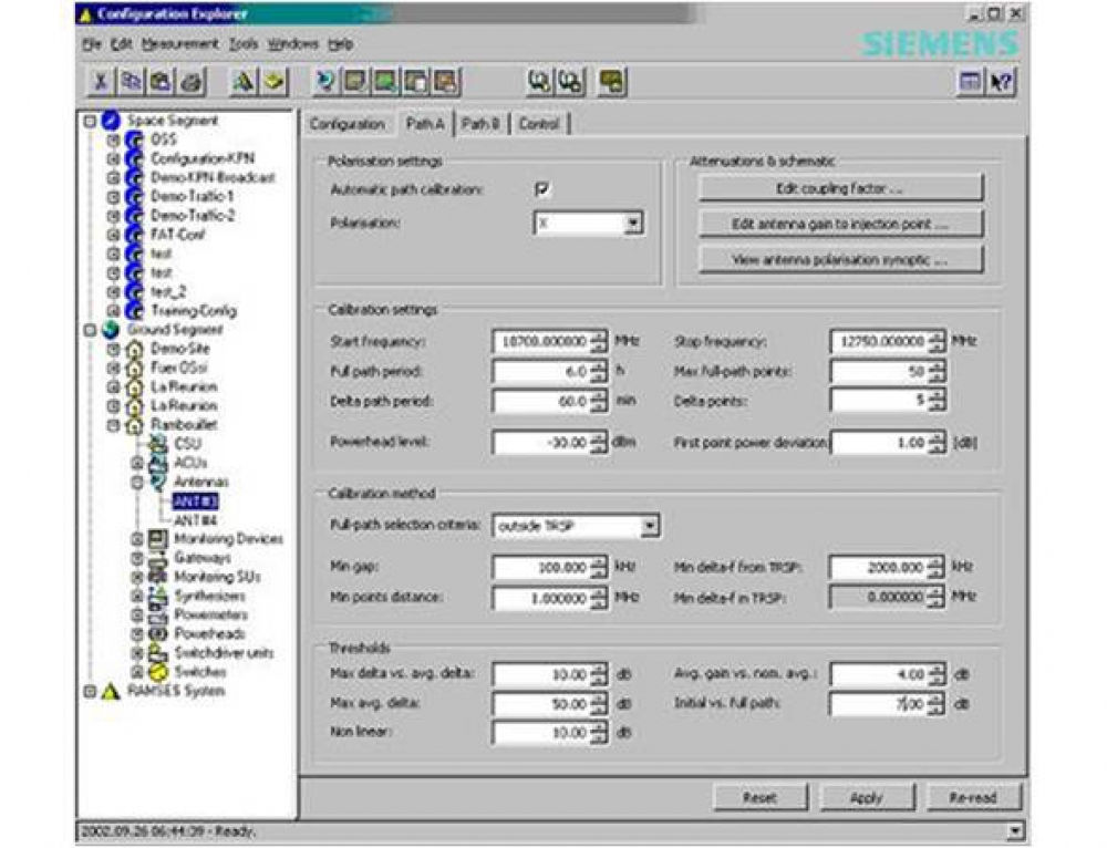
In order to ensure maximum accuracy, SkyMon has an ingenious built-in calibration subsystem that is capable of automatically calibrating the complete RF downlink path from the antenna feed-up to the monitoring devices (if supported by the RF hardware). Thus, with minimal system performance impact, SkyMon is capable of providing accurate satellite level measurement results and long-term stability.
SkyMon earth station calibration
Equipment calibration
WEB Interface
Web access to the system is provided via Remote Application Sharing technology. With this approach the SkyMon client application can be virtualized and accessed from any device using an Internet browser. Together with the highly flexible user rights configuration, this solution offers customized web access providing the same client GUI as available on local installations.
Transponder Performance Monitoring
A transparent satellite transponder typically processes the received signals in terms of amplification, filtering and frequency translation before the signals are retransmitted to earth station receivers.
For several reasons a satellite transponder is often required to provide maximum output power. Therefore, it should be operated at its saturation point. One reason is to ensure reliable reception of the retransmitted signals at the earth station receiver even if it rains (usually referred to as rain margin). On the other hand, for many applications the size of the receive antenna aperture is limited due to economical and building permission constraints. Therefore, the receive antenna often has to be as small as possible. However, often a minimum size is required, since small apertures will lead to impaired signal discrimination due to adjacent satellite interference.
At high power levels the relationship between input signal power and output signal power in satellite transponder amplifiers becomes increasingly non-linear. This behavior can be seen in the gain transfer curve and varies, depending on the design and technology of the transponder applied. The signals’ mean power level at the gain transfer curve on which transponder operation is based is usually referred to as operating point.
In case of high-power transmission, the signal tends to show non-linear distortion, jeopardizing the quality and reliability of the satellite communication link. With regard to digital transmission, many services are sensitive and susceptible to amplitude-to-amplitude (AM/AM) and amplitude-to-phase shift (AM/PM) conversion introduced by high power amplification. The corruption of the transmitted signal leads to increased intermodulation components, which deteriorates system quality parameters, such as symbol and bit error rates (SER, BER). Consequently, a compromise has to be found between high transmission power levels (increasing Eb/No) and increased intermodulation components, caused by operating the satellite transponder beyond its linear gain limitation (increasing SER, BER). Whereas usually some compression is tolerable, operation beyond a certain level of saturation leads to unacceptably high signal distortion. The goal is to have an optimum operating point, which is determined by finding the maximum output power, while maintaining the specified BER.
Furthermore, satellite providers want to be able to monitor the transponder transfer characterization and compression behavior in order to provide sustained reliability and quality of service to their customers.
To make this possible a new foreground mode has been created: the Transponder Performance Mode. It displays a diagram of output vs. relative input power of a selected transponder. Together with the gain curve, the phase shift as well as the:
• Point of operation (mean power EIRP)
• Delta from linear operation
• OBO from 1 dBCp, if applicable,
is displayed.

The figure above shows an example of the measured gain transfer curve of a transponder loaded with a single carrier and operated close to saturation (OBO: 0 dB). The AM/AM characteristic is indicated in blue, while the AM/PM characteristic is indicated in red. The point of operation (mean power) is indicated by the pink mark and the saturation point by a green mark on the AM/AM curve.
Measurement Devices
With the SkyMon family you do not depend on just a few specific measurement devices. SkyMon comes with several drivers for supporting a great variety of devices and, if necessary, even more instruments can be integrated into the driver library. Please contact us for detailed information and data sheets.
Related resources
Space refereces


